OP
Thread Starter
#41
- Member ID
- #1044
- Messages
- 8,248
- Reactions
- 37,041
- Likes
- 352
- City
- Riverside
- State
- CA
- Country
- United States
- Vehicle
- 2015 Dodge Charger Hellcat!
Thread Starter
#41
Upon further inspection/thought:
How did you end up at the 10K ohm, 7W (fixed) wirewound resistor calculation?
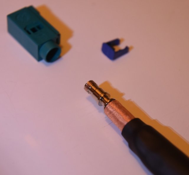
Reason I ask, this will work fine for the purple (FAKRA D) connector, however, per my earlier comments in this thread, *IF* I need to also block the pink (FAKRA H) connector, I'm not sure if the resistance would be the same, and not sure how to calculate.
Obviously would need a different plug housing also.
How did you end up at the 10K ohm, 7W (fixed) wirewound resistor calculation?
Reason I ask, this will work fine for the purple (FAKRA D) connector, however, per my earlier comments in this thread, *IF* I need to also block the pink (FAKRA H) connector, I'm not sure if the resistance would be the same, and not sure how to calculate.
Obviously would need a different plug housing also.
In the FSM, under cell troubleshooting, they call out for a specific miller tool, to load the cell module, once the antenna is removed. Simply unplugging the antenna is NOT recommended, as it can cause damage to the mode.
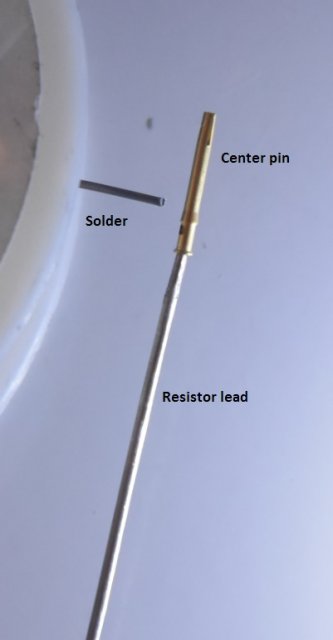
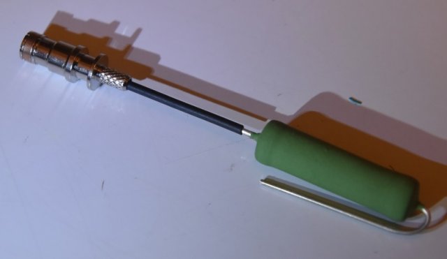
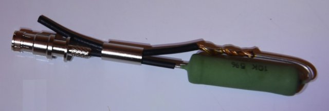
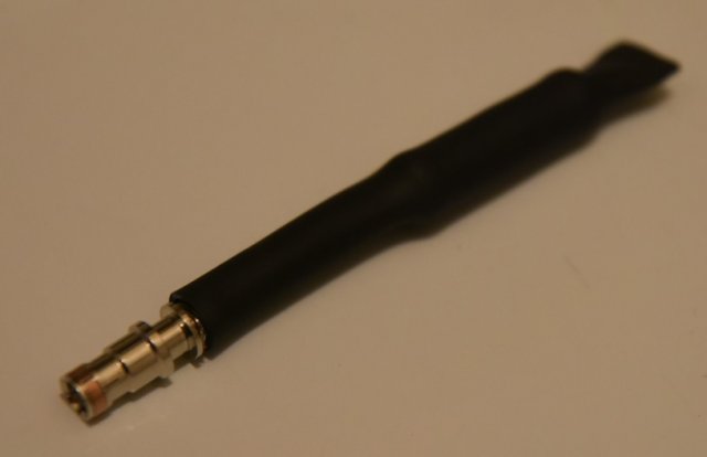
The Miller tool has a load of 10k ohms. You could use a much smaller resistor, but it is difficult to add the faraday material to a 2 watt resistor.
I went with a WW resistor, because I wanted a 1%, close tolerance load. There is a small +/- window that HAL9000 is looking for. Anything outside that range and you will throw a code.
Last edited:
-
 1
1
- Show All