Attached some pictures of the install today.
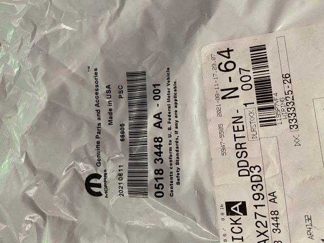
Pic 1 - Mopar Part #
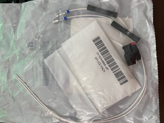
Pic 2 - Contents of package; connector, 2 wires, 2 heat shrink tubes and 2 wire cramps (not in picture, not used)
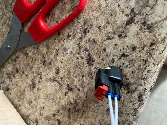
Pic 3 - You have to insert each wire (blue end) into the connector. Looking at Pic 2, you can see on the blue end of the wire, that the end is a box shape. You have to make sure you line them up correctly before inserting into connector. If you look in the connector, you can probably reason out how it should slide in. It doesn't take much effort to push it in, and if it does you likely have it inserted the wrong way. You will hear an obvious click once the wire is inserted correctly.
Honestly, if you were able to source these wires on their own, you really wouldn't have needed to purchase this package. You can reuse the old connector by popping out the front plate of connector and sliding the old wires out.
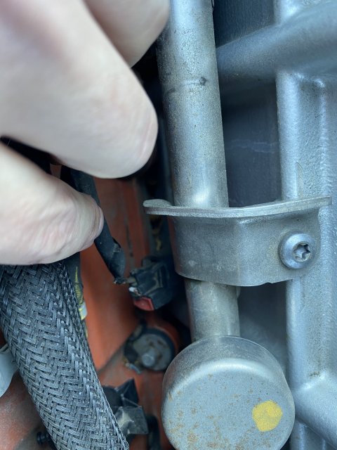
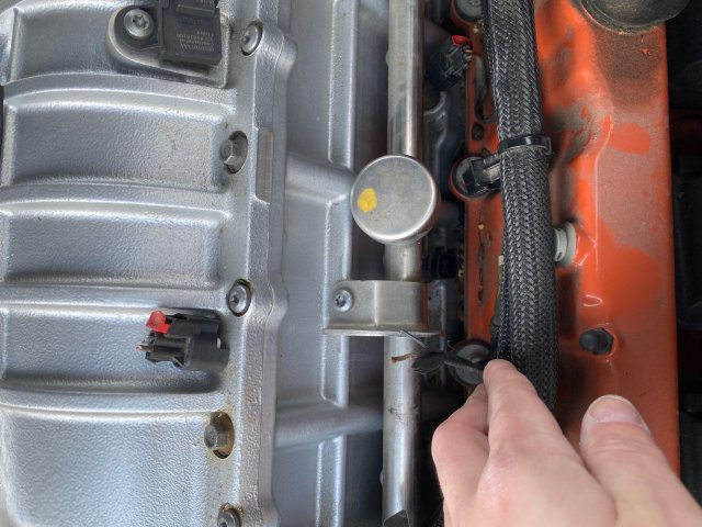
Pic 4 - Old connector cutoff, existing wires exposed with some of the wire wrap removed. Brown wire will coincide with the far left wire on the new connector (since both wires are white on the new one). When connected, the red locking tab is on the right, then are two wires to the left of that.
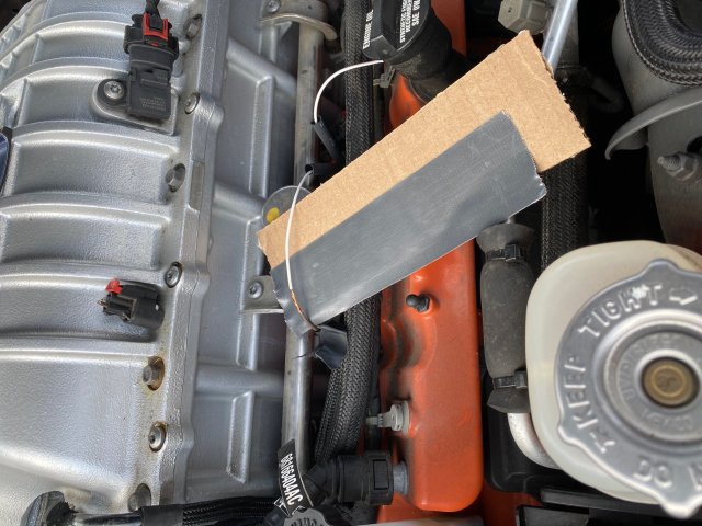
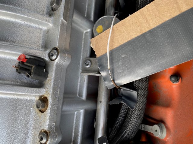
Pic 5 - There's not a whole lot of room to work here. I took off about 1/2" of wire insulation from the existing brown wire and left white wire. I gave myself a couple of extra inches of room on the white wire side incase this would have to ever be done in the future. MAKE SURE YOU PUT HEAT SHRINK TUBES ON WIRE PRIOR TO BRAIDING/SOLDERING. I braided the two wires together and put a piece of carboard with thick gorilla tape under in prep for soldering.
Pic 6 - Picture of soldered wire using very fine electrical rosin core solder (leaded

. I put the solder iron on the bottom of the braided wires to heat up the copper. Once hot, then press the solder on the top of the braided copper, which then melts into the wires forming a solid connection. You don't want to put the solder directly on the solder iron tip and drip it on the wire. That can result in ineffective, cold solder.
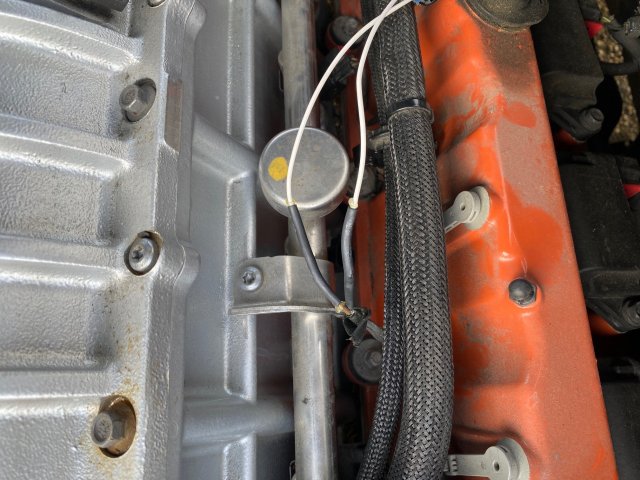
Pic 7- Both sides soldered and heat shrink tubing shrunk. The tube itself was a bit long for this application. The solder connection point is not exactly in the center, as I would have to shrink over a longer portion of the old wire (for which there is limited remaining line left). In case one day I need remove; I'll still have some more room to pull back on the old wire to do it again.
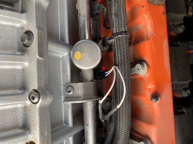
Pic 8 - Connector reinstalled; as you can see the line is a few inches longer than original. Also as this point, I started the car to ensure it was operating properly. Removed the CEL's and restarted again to ensure nothing came back.
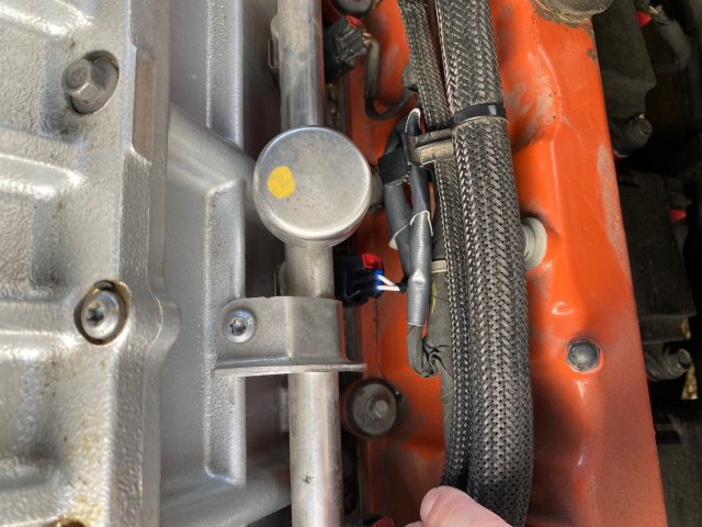
Pic 9 - I wrapped everything with electrical tape, and then did a top layer of gorilla tape just for the heck of it. I was able to route the slack through the loom clip to keep the extra slack out of the way.
Easy and straightforward...just limited room to work / solder with not much slack available on the original harness side.

